
Figure 1: Aircraft OHLG.

Figure 2: How Flying Aircraft OHLG.

Figure 3: Top View from the Wing.
Maximum thickness is 30% of the LE indicated by dashed lines. Aspect Ratio (AR) is a wing slenderness factor. AR at OHLG aircraft by 5 to 12. While the AR in an aircraft that is controlled by radio (Radio Controlled RC Airplanes) by 7 to 10.
The formula is the aspect ratio AR = b ^ 2 / S where b is the wingspan or the distance between the wingtip to the other wing on wing. S is the area of the wing. To determine S with trapezoidal approach below.

Figure 4: Trapezoid.
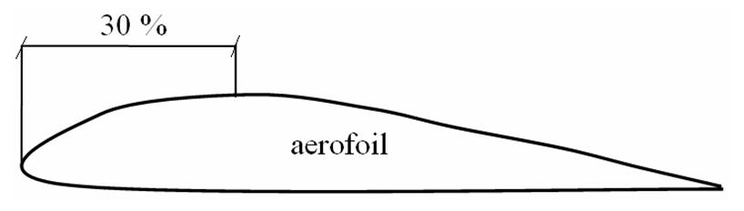
Figure 5: Aerofoil.

Figure 6: Balsa Hardware mounted on LE.
Next enter the stage of manufacture of the fuselage. The fuselage is made of Balsa wood is hard and shaped like the image below.

Figure 7: Body Aircraft OHLG.
The distance the nose to the LE of the wing chord. Fuselas length of 5.25 multiplied by the wing chord.
Then create a stabilo and fin. Stabilo is the horizontal tail while fin is the vertical tail. Stabilo and fin are made following the instructions below.

Figure 8: Stabilo and Fin.
Stabilo wingspan of 33.3% of the wingspan. Stabilo chord of 75% of wing chord. Wide fin 33.3% of the stabilo area as shown in figure 8 (shaded part).

Figure 9: Gap between Wing and Stabilo.
Installation of a stabilo on the body with a gap between the wing and the stabilo around 1.5 to 2 cm.
The next step is mounting the amplifier on the wing. The purpose of this amplifier installation so that the wing is not damaged when it made the flight.

Figure 10: The amplifier on the Wing.
Amplifier installation done under the wing surface as shown in Figure 10. Direction of the wing amplifier fiber that is parallel to the fuselage.

Figure 11: Installation of Aircraft fin.
Installation of an aircraft fin as shown in Figure 11. In this way more easily in moving the rudder and elevator. To get the aircraft's outer skin silky smooth refinement performed. Smoothing using a plastic that is dissolved using a solvent of plastic. Usually plastic solvent that is used branded Herin. Smoothing is done like painting wood and sanding step is then performed.
The next step considers the aircraft to determine the location of the center of mass or center of gravity (cg). This step is often called the Weight and Balance (WAB). WAB goal to get the cg location as far as 30% of TE as shown in Figure 12. Weight settings by adding a thin metal on the nose of this plane.

Figure 12: Position c.g against TE.
Tidak ada komentar:
Posting Komentar